After years of listening to my tube headphone amplifier, I decided to build this one. I wanted a change from the warm sound of the tube, to something more sharp, precise, and detailed. But mainly out of sheer curiosity.
In electronics, and with every other hobby you don’t need to have a specific reason to build something. Just enjoy the journey building the thing and have fun.
On to the amp.
Surprisingly, the TPA6120 IC truly delivered the sound quality I was expecting (and read about). The sound is crystal clear, very detailed and has an excellent dynamic range.
You will find it’s used in thousands of professional or semi-professional builds across forums, blogs, online shops, and whatnot. Paired with the famous Burr-Brown opamp the commonly used OPA2134, the amplifier delivered such a great sound.
Disclaimer: This is by no means audiophile build that takes into consideration “everything” ranging from the type of power supply cable down to capacitor and resistor brands. And please consider it as such, just a hobbyist building an amp.
I’m well aware of the whole audio world, the tech, amps, preamps, tubes, caps, and everything related. I’ve built a couple of amplifiers myself both as a hobbyist and professionally by client requests.
With that aside, let us continue.
We will start with the datasheets of both the TPA and OPA chips, which you’ll find on these links:
http://www.ti.com/lit/ds/symlink/tpa6120a2.pdf
http://www.ti.com/lit/ds/symlink/opa2134.pdf
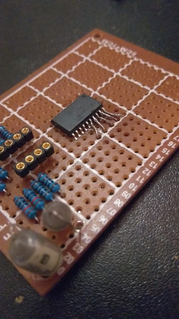
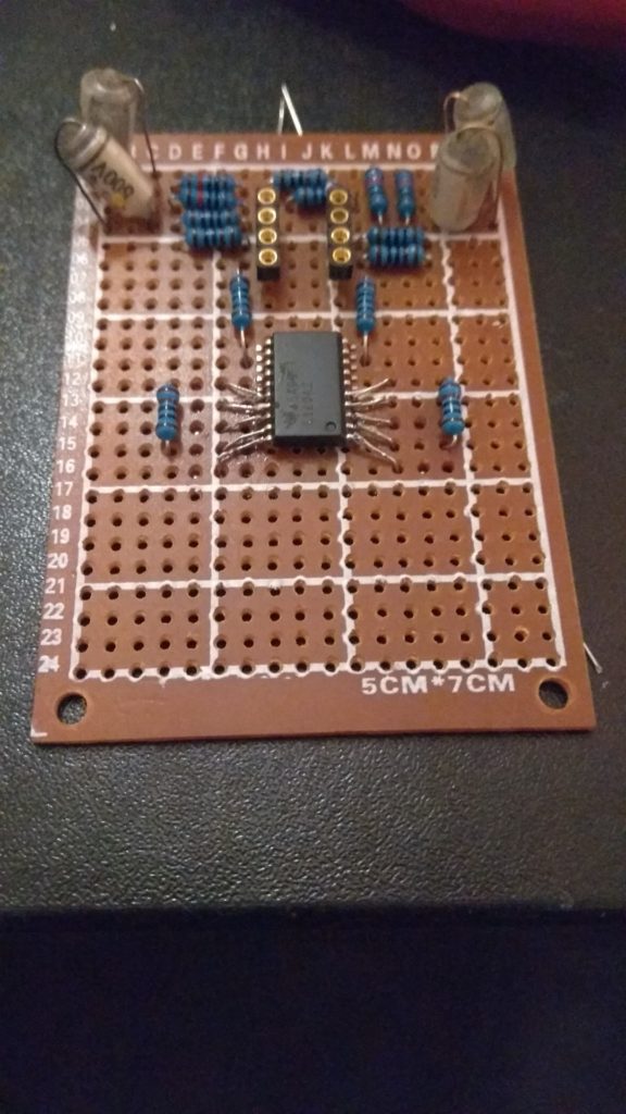
The TPA6120 that I’ve used comes in the 20pin SOIC package and the OPA2134 in 8pin DIP(good for experimenting). There are a whole lot of options for building it. Going all SMD, mixing them(like this one), using adapters, it’s up to you to decide.
The schematic that I’ve used is this one and the credit goes to the author:

The power comes from symmetrical +/- 15V DC supply. I’ve used 7815 and 7915 regulators and a small 4.5W transformer.
(I will group the photos in this post as to have them in manageable chunks instead of all ~50 photos loading full res. in one go).
I’ve built this on a simple perforated board. The resistors are metal film 1%, the 100p caps are styroflex, the output ones added are OSCON Panasonic type, gold pin socket for experimenting with preamp chips. The TPA is soldered by what I call reverse-dead-bug, yeah it’s weird I know. But it works! There are no oscillations or noise from it, the leads are extremely short.


First measurement. I’ve used my 2x70MHz GwInstek oscilloscope, and signal generator to have some basic knowledge if everything works as it should.


The audio frequency response graphing and measuring was done manually. Going through 20 frequencies and gathering the output specs. I’ve compiled this into simple graphs in excel for easier reading.
It boils down to x2 or 6dB gain, measured from 1.23V taken as the reference input voltage. The response was somewhat flat with some (minor) increase in bass frequency. Which to be honest makes no difference to me.

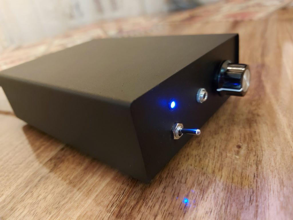
The enclosure that I’ve picked up for this project is really spot on. It’s really compact with small dimensions that nicely fit on my desk.


But the 40x140x100mm box did make this a bit tough to try and fit everything in it. I needed to fit the transformer, the two boards, and plus the speaker protection circuitry. It was a challenge!
I started off with the disassembly of the enclosure, gathered the components, added a fuse, and prepared for drilling the panels.


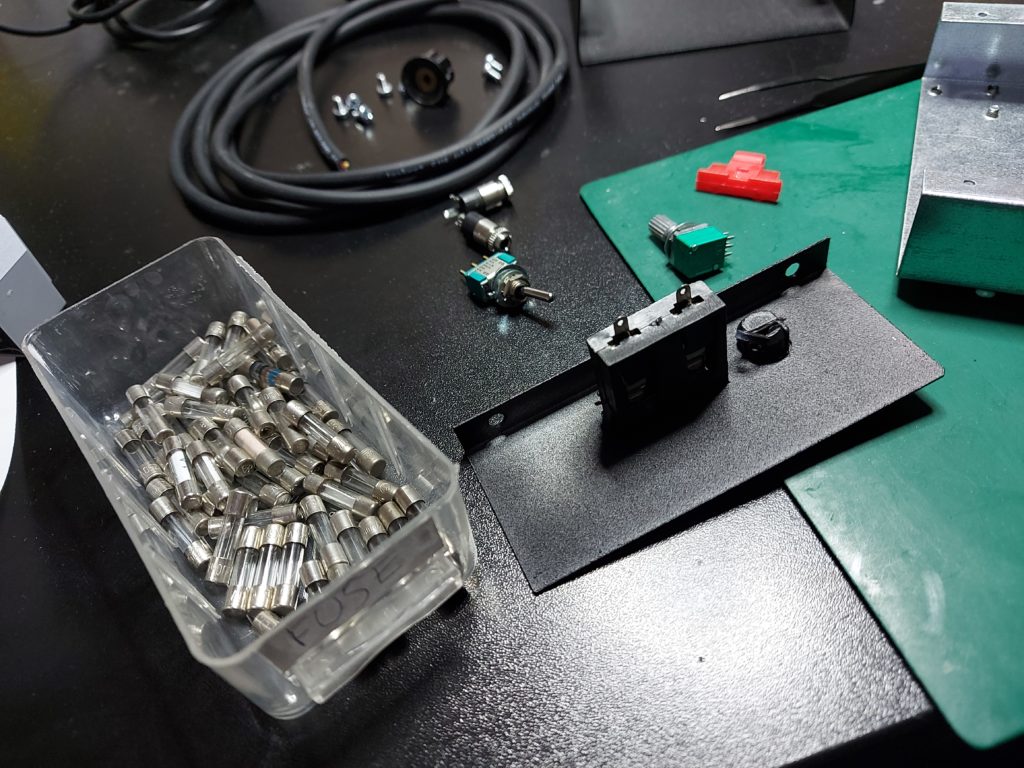
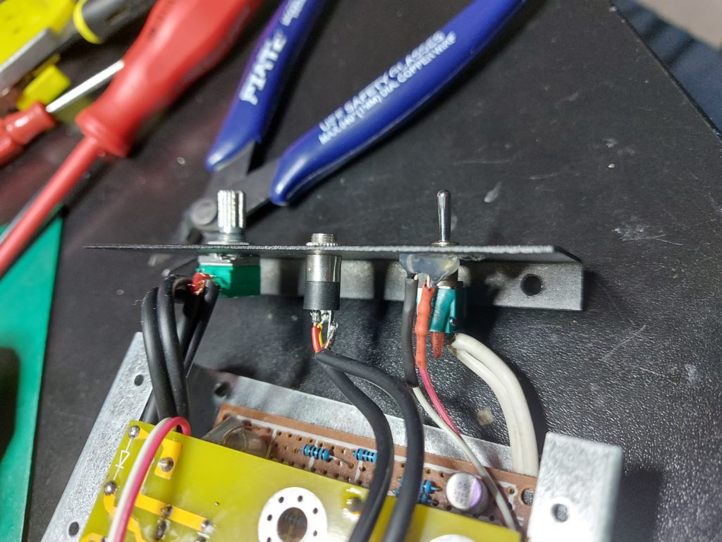
The front panel has four holes, for the pot, output jack, led indicator and the mains switch. I used a caliper to correctly measure where everything should be. The center punch is key here since if your drillbit slips even a little you can destroy the panel.


The back panel had only one hole that needed to be drilled for the input jack. I’ve chosen to place it in the opposite corner to avoid the mains cable as much as possible.

The guts and the whole *Welcome to the jungle.mp3* mess. Along with another test to see if there is a short or something has blown up :). The yellow PCB – the top of the sandwich is the speaker protection. It uses the UPC1237 chip, adds delay to the output and detects if DC voltage is present so it can cut off to prevent damage to your headphone/speakers.


All closed up and final pictures.