In this post, I will explain how to repair a Cisco 2000 (Cat2k) series switch that suffers from bad DRAM memory.
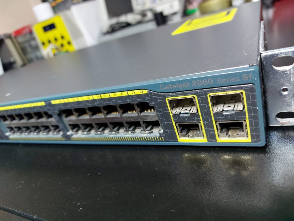
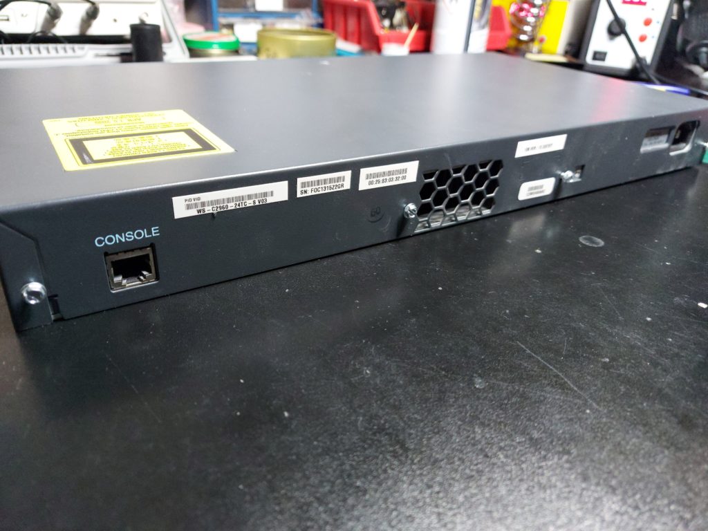
The exact model of the switch is WS-2960S-24TC-S.
Some switches that have their memory chip manufactured between 2005 and 2010 can suffer from this component failure.
Initially, the switch will work fine and without issues until there is a need for a reboot, update/upgrade or shutdown. After that, the memory of the switch will give up and there will be a failure to boot.
Usually, the symptoms are: all status LEDs will light up but there will be no other activity, you can’t SSH/telnet to it, the console gives no or broken output, connecting a cable doesn’t get registered…
You can read more on the Cisco website, here are two links that cover it:
Field Notice: FN – 63744 – Cat2K Might Fail to Boot After a Power Cycle – Replace on Failure
This is a perfectly fine switch that can still be used, albeit not in a datacenter. Still, because of one single IC issue, we shouldn’t just throw the switch to the bin.
There are thousands upon thousands of equipment thrown away every day because of some small issues with its hardware or software. I’m highly supportive of the Right to Repair and try to minimize the e-waste impact.
Me
That aside, let’s go below Layer 1. On to repairing!
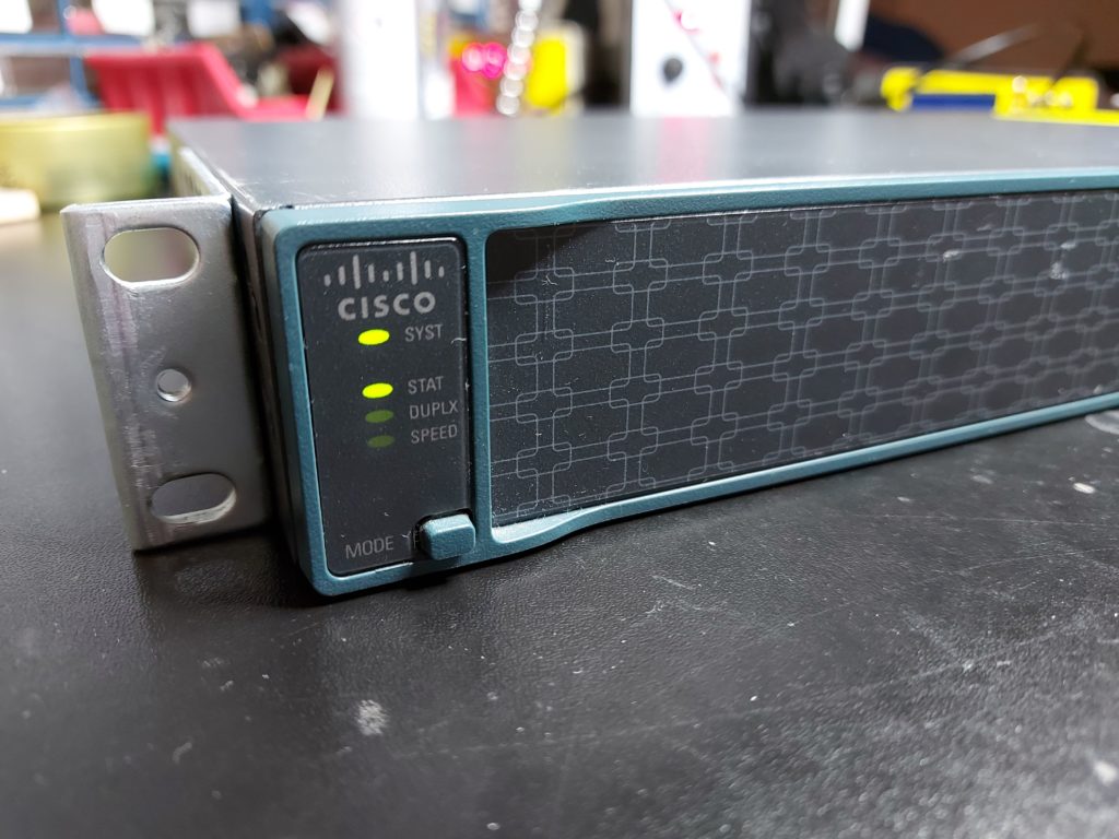
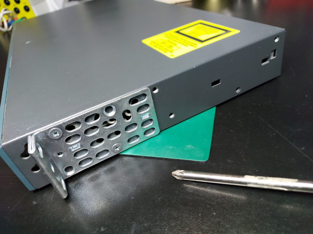
The switch in question.
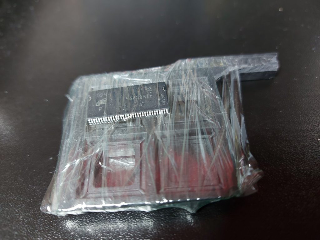
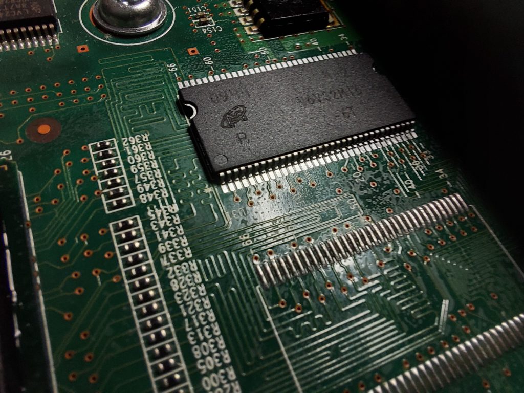
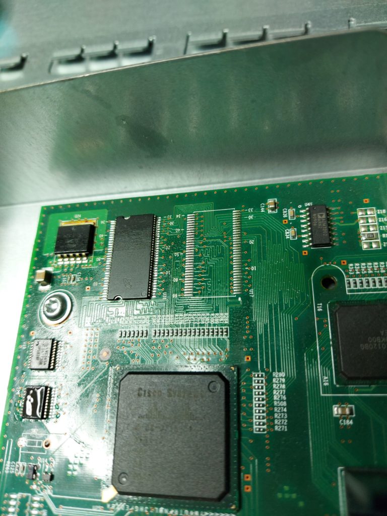
The original and the replacement DRAM is made from Micron, it’s an MT46V32M16 32MB DRAM in TSSOP 66pin package.
(as you can see the “packaging” that the chip arrived isn’t quite the special one… But hey, at least the pins weren’t bent :))
This switch current issue is that all staus LEDs light up, and there is no console output. See the pic below:
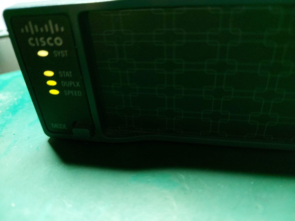
The switch will just hang on this state and nothing will change even if you leave it powered on for hours.
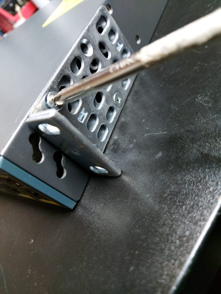
On to disassembling:
First, remove the side screws that hold the mounting brackets
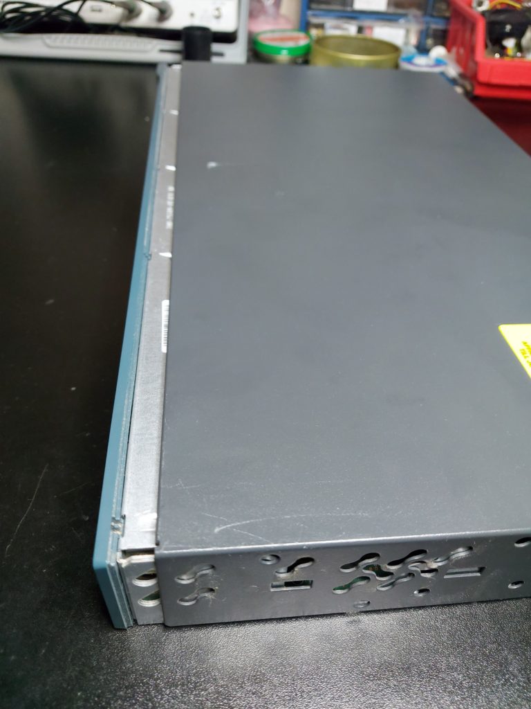
Turn it’s back towards you, and remove the four screws that hold the cover.

After that just slide the cover to the back and voila.
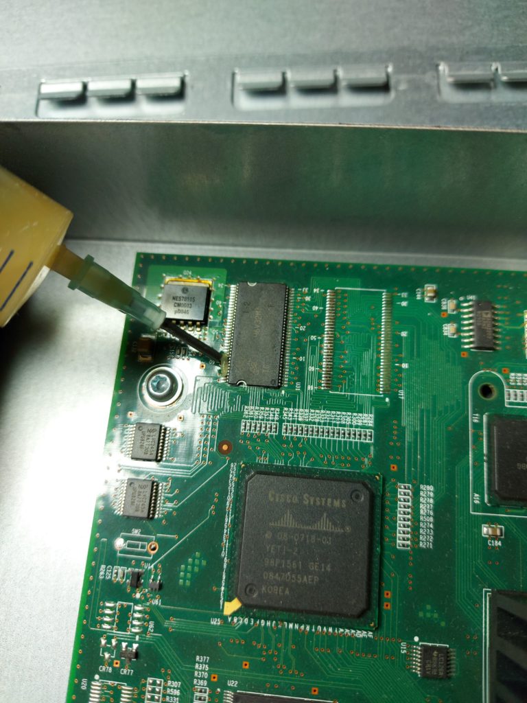
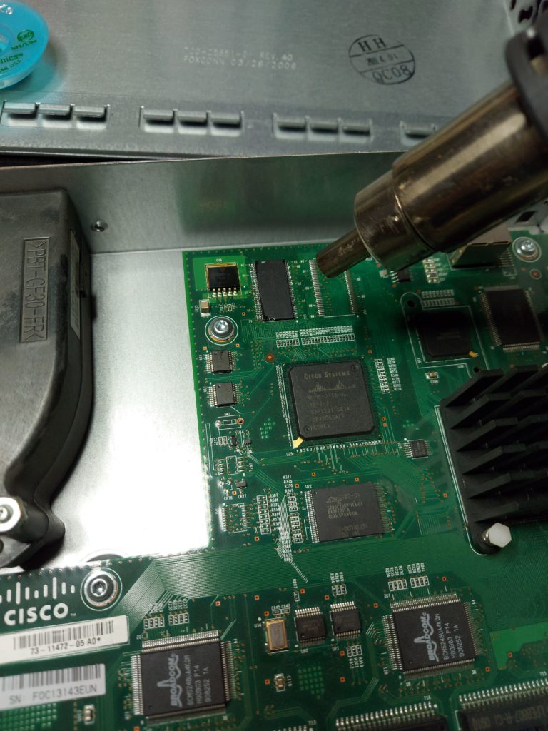
In all it’s glory

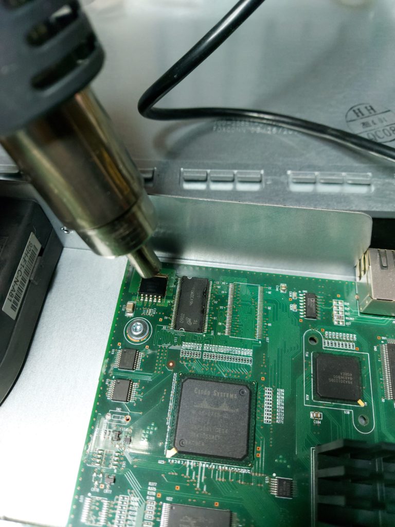
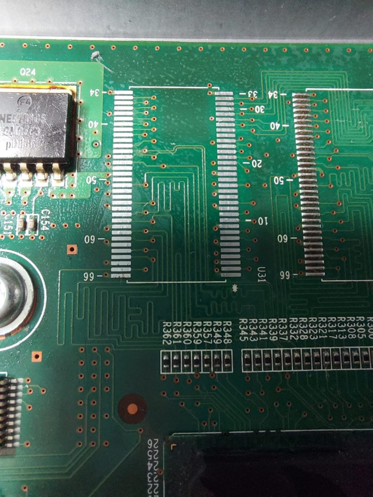
The DRAM chip we are looking for it’s located right of the cooler, and it’s marked here.

Let’s proceed to desoldering and replacing the bad memory.
Add a bit of flux to its pins. This will help remove the oxidation from the solder and aid in greater temperature spreading.
Get your hot air station and some tweezers.
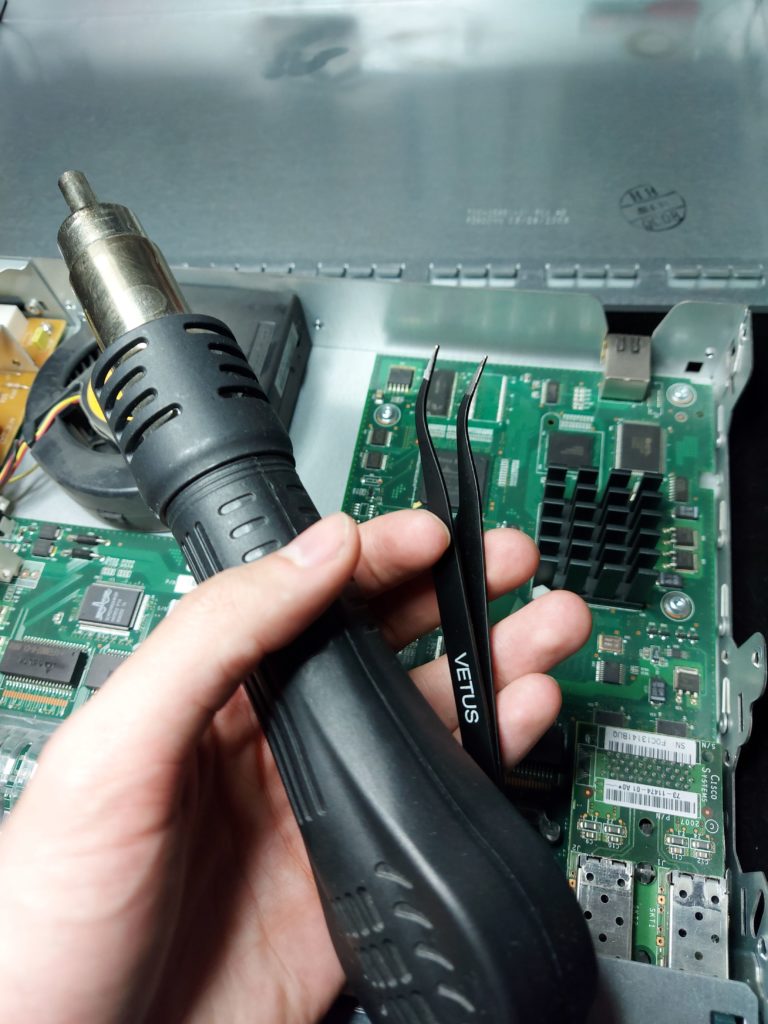
Carefully heat the chip and the surrounding area, you’ll see the solder liquifying and changing its reflection(it will go from matte to more glossy like). Gently probe it with the tweezers to see if the chip is moving, but carefully enough since it’s very easy to rip a pad and make the whole repair a failure.
There it goes
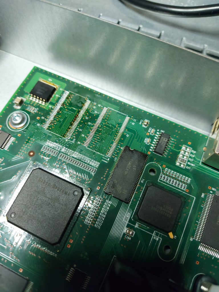
There are several methods that can be used to solder the new chip and its just a matter of preference. But I personally choose to clean up the pads and manually using a soldering iron to go through each pin – resoldering the new chip.
Cleanup before
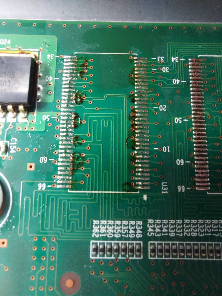
And after
Bad chip on the left, the new one on the right

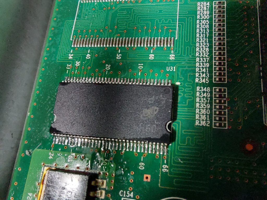
Aligning the pins to the pads, this is a tricky part. Note the white star on the board and the dot on the chip. That indicates the first pin. Be careful not to solder it backwards.
What I do next is to solder the four pins in each corner, so that the chip will be fixed to the board and make it easier for me to solder the rest of them. Note the first and the last pin from this side.

Now I manually solder each pin. I know it looks tedious but it’s done quickly if you know what you are doing. Some pins will look that they aren’t soldered, do not worry since you can reflow the whole chip with the hot air station.
Visually inspect the pins, ideally with a microscope but a magnifying glass will also work.
Reflow
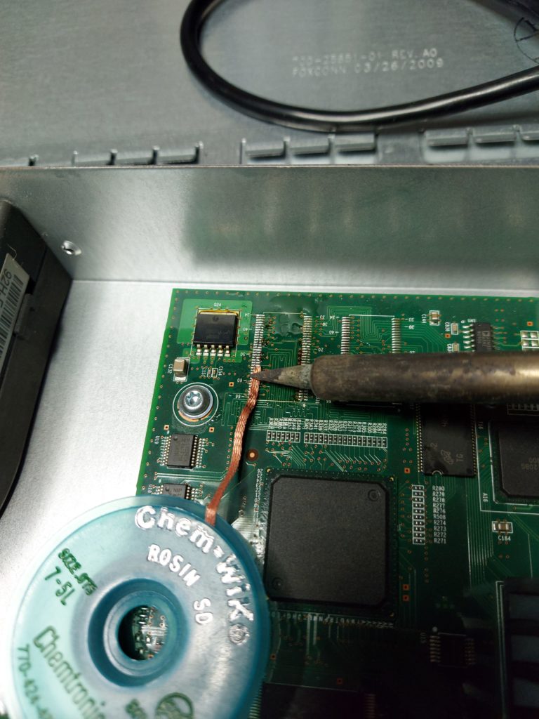
Second cleanup
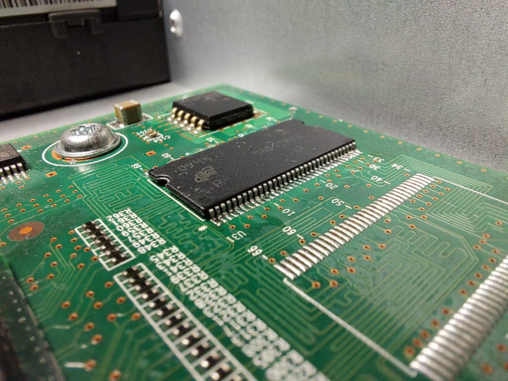
Now it’s time to try and see if it boots up 🙂
There we go, the switch booted up. Now let’s check if we can get console output. You can see the blue cable in this picture.

The output from MOBA terminal
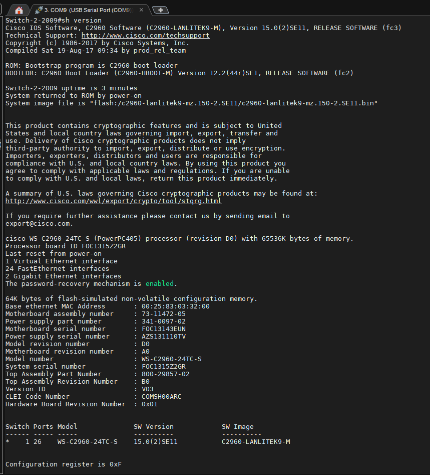
Voila, for $2 replacement chip we got the switch up and running again.
We are still not done, on to assembling it again. You should have the two brackets and eight screws. Two for each bracket and four for the top panel.

Screw back the cover first, and then the side brackets.
That’s it 🙂